- Please confirm the connection between the optical RPM probe and the circuit has been set up properly following the setup guideline come with the optical RPM probe
- Please confirm that the optical RPM probe has been powered by a 5V power properly. For the customer who purchased the Series 1585 and Series 1580 with v1.8 or higher version PCB, the 5V power output has been integrated to the S1 port on the circuit. Please put the jumper to the proper position following the instruction on the PCB. For the customers who are using the Series 1520 or 1580 with lower version circuit, please use your own power supply to power the optical RPM probe.
- Please check the distance between the optical sensor on the optical RPM probe circuit and the reflective tape on the motor. It needs to be less than 5mm.
- Please confirm the length of the reflective tape on the motor is longer than 10mm
- You can do the following steps to verify the optical RPM probe circuit is functional
- Connect the optical RPM probe on the Dynamometer circuit following the guideline
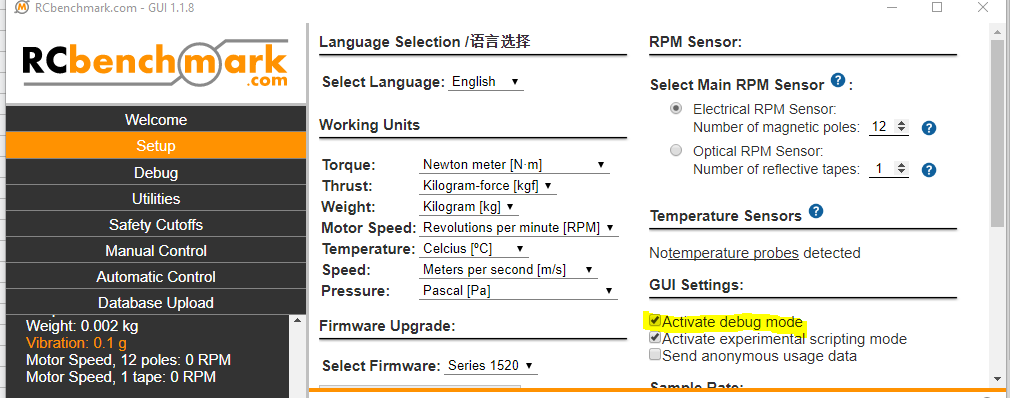
- Connect the circuit to the RCbenchmark GUI and activate the debug mode on the GUI. The debug mode can be activated in the RCbenchmark GUI -> Setup -> GUI Settings -> Activate debug mode
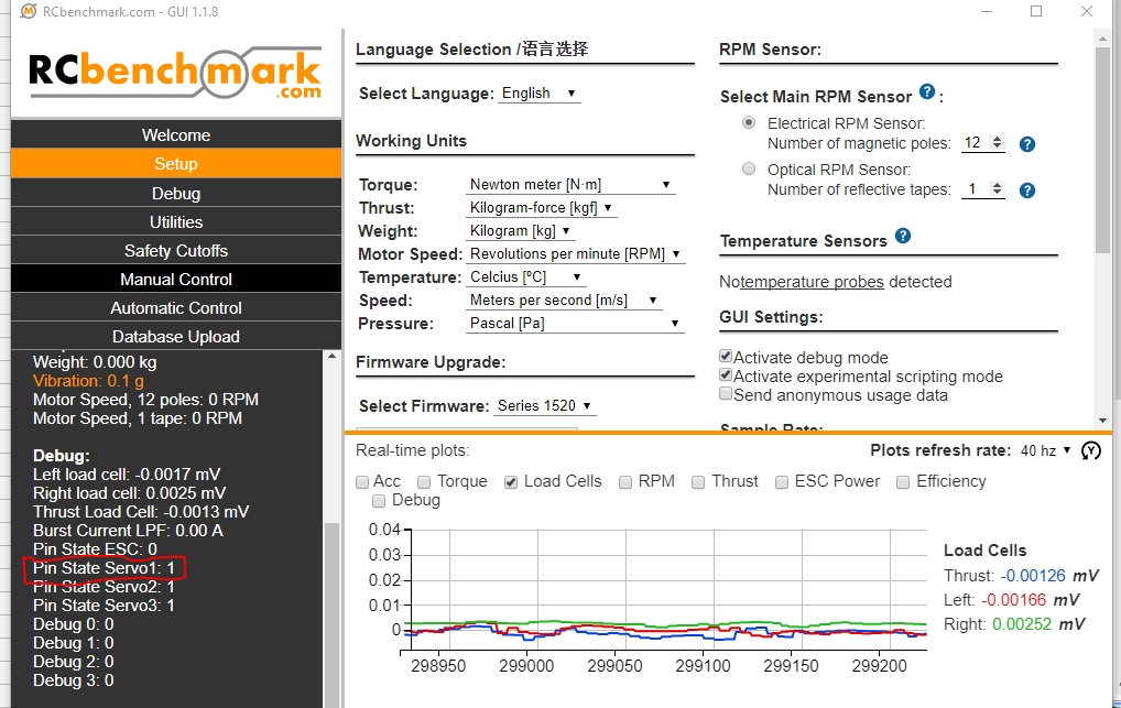
- Put a reflective tape in front of the sensor on the optical RPM probe and then remove. If the optical RPM probe circuit is functional, you will find that the number on the Pin State Servo1 will change.
- If you find that you are still not able to read any data of the RPM from the GUI, please send us the invoice when you purchased our product, the picture of the circuit, and the description of the issue you met to support@tytorobotics.com. We will give you suggestions for further troubleshooting and solutions for the issue you met.